Our challenge: 280,000 boreholes on the A24 Blankenburgverbinding
We will be drilling around 280,000 protruding reinforcements and brackets in the underwater concrete floor of the Maas Delta tunnel and Holland tunnel on the A24 Blankenburgverbinding. It is a job that must be carried out with the utmost precision, as the rebar cage in the underwater concrete must not be touched at all. We have found a solution to that challenge.
Autopilot? Not a chance.
The construction of the Maas Delta Tunnel is divided into eighteen compartments, including two 200-metre zinc elements. Before the underwater concrete floor is poured into the sixteen compartments that will not be submerged, the reinforcement cages are installed up to thirty metres underwater using a dragline excavator. They are positioned over the anchors by divers. Once the cofferdams have been drained, the concrete can be poured, allowing the protruding reinforcements and brackets to be drilled safely.
In theory, drilling the approximately 280,000 protruding reinforcements and brackets is fairly easy to automate, as the boreholes need to be of equal depth and spacing. In practice, it is not that simple. As the project progresses, we sometimes make small changes to the structure, causing the reinforcement cages to deviate from the initial design. Small deformations may also occur during the moving and transporting of the cages. As such, we cannot drill the holes on autopilot without risking hitting the rebar.
Avoiding conflicts
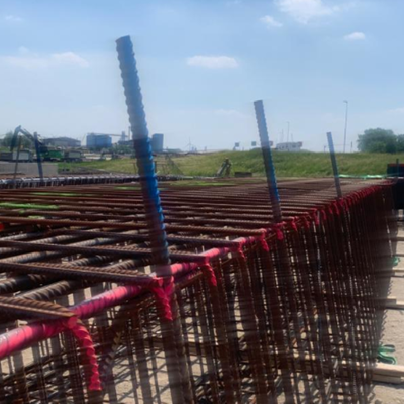
We attach several visual indicators to each reinforcement cage, which we use to determine the final position of the cages. The indicators, consisting of rebar, will protrude above the concrete floor after the underwater concrete is poured.
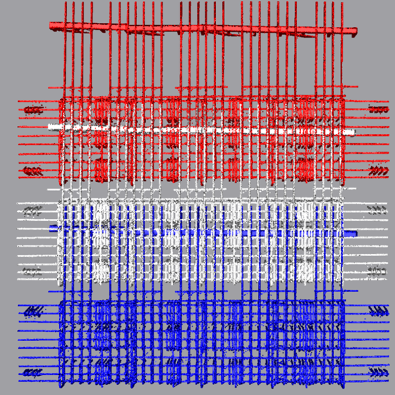
We make a 3D laser scan of each cage before it is put in place. "This documents the so-called ‘as-built’ form," says Dave van Dreven, Project Coordinator of Measurement and Geodesy at DIBEC, part of Ballast Nedam. "The entire upper mesh and visual indicators are recorded in one measurement, and each cage gets its own file. The cage is only lowered into place underwater after scanning."
The 3D scan allows us to calculate the exact locations of the boreholes in our software. We merge each cage's scanned point cloud with the drawing of how we planned the boreholes in theory. By comparing the two, we can check whether every theoretical borehole will miss the rebar in practice. We are basically checking to make sure there is no conflict. If there is a conflict, we adjust the location of the borehole according to previously agreed design specifications and tolerances to ensure a match with the 3D scan of the cage—the as-built form.
When the cofferdam is drained, the concrete floor becomes visible. At this point, the reinforcement is in the concrete, but the visual indicators are still visible. Our measurer can measure the visual indicators to determine the actual position of the cage. This allows us to compare the visual indicators on the scanned, as-built model with the measured actual locations in the cofferdam. Dave van Dreven: "This method results in fewer errors and lower costs. It gives us a detailed picture of the exact location of each reinforcement cage and each reinforcement bar in the upper mesh in the concrete. This step also includes future boreholes, so they are now in the correct measurement system as well."
280,000 coordinates
The cages are connected with lengths of rebar known as "welding lengths”. We gradually combine all the scans for each part of the floor to map out the welding lengths of the upper mesh. Each borehole is assigned a coordinate, ensuring that the welding lengths are not hit.
These coordinates all have to be measured accurately, for which we use the known measuring points in the field: the project base network. The network is included in the Netherlands RD/NAP coordinate system and serves as the basis for every construction project's digital design and physical execution.
A semi-automated version
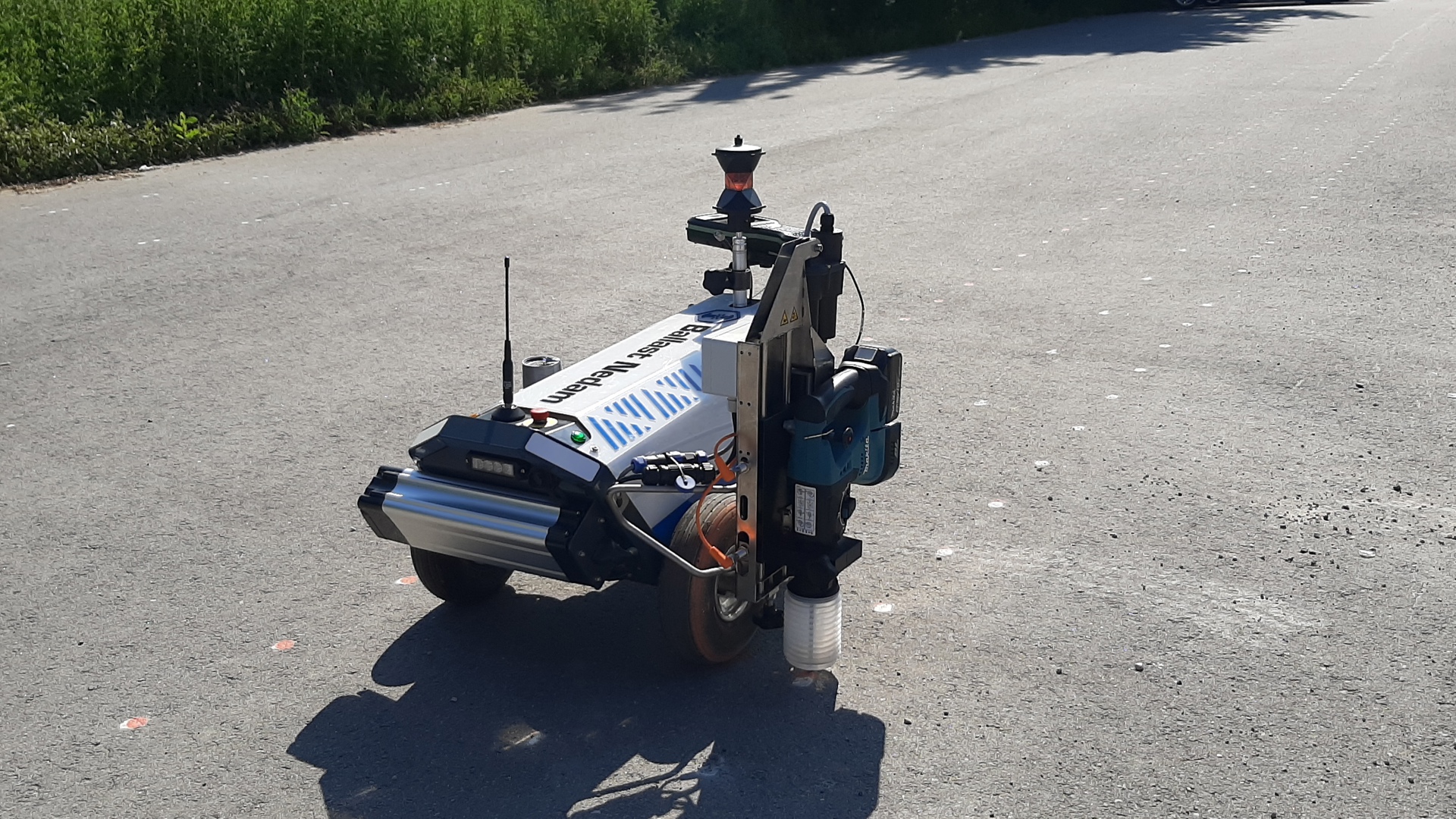
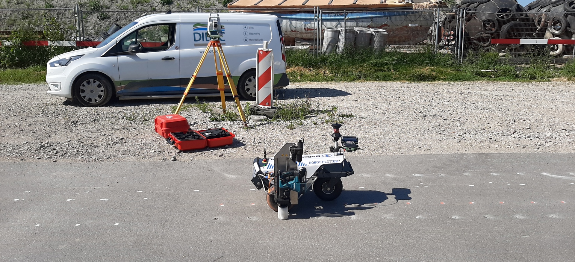
When all borehole positions are correct, we mark the locations of the holes on the dried concrete floor of the compartments using our Robot Plotter, an electric robot that can plot lines and points. The robot is controlled by GPS or Total Station, depending on the required accuracy and environment. For the A24 Blankenburgverbinding, the system will be controlled by Total Station to achieve the highest possible accuracy.
Clemens Tierie, Measurement Manager, sees the benefits of the robot plotter. "We can work more efficiently, allowing us to get the job done four times faster. We do this by exporting the retrieved coordinates to our measuring equipment, preparing the points in patterns according to feasibility and borehole type."
We have augmented the Robot Plotter with a module that can mark the individual coordinates with paint dots. We can distinguish between the types of boreholes by using different paint colours. Water, dirt and other on-site conditions can cause the paint to fade, so we have developed an automated system that not only determines the drill hole and marks it with a paint dot but can also drill a small hole at the correct location. A dowel is inserted by hand, protruding around one centimetre above the concrete, allowing us to clearly see the drill hole.
Space for further development
"This process on the A24 Blankenburgverbinding combines our staff’s extensive experience with the latest developments in our field," says Clemens Tierie. "This combination will enable us to solve the complex challenges on our current and future projects. That is why we continue to test and innovate. For example, we are testing the possibilities of Augmented Reality at the A9 Gaasperdammerweg project in Amsterdam, and we will soon be able to take measurements by drone almost everywhere at the Prinses Amaliahaven in Rotterdam. We combine expert knowledge with technology and continue to innovate during our projects."

